
from machine import Pin
import utime
led_green = Pin(15, Pin.OUT)
led_red = Pin(14, Pin.OUT)
led_blue = Pin(13, Pin.OUT)
while True:
led_green.on()
utime.sleep(1)
led_green.off()
led_red.on()
utime.sleep(1)
led_red.off()
led_blue.on()
utime.sleep(1)
led_blue.off()
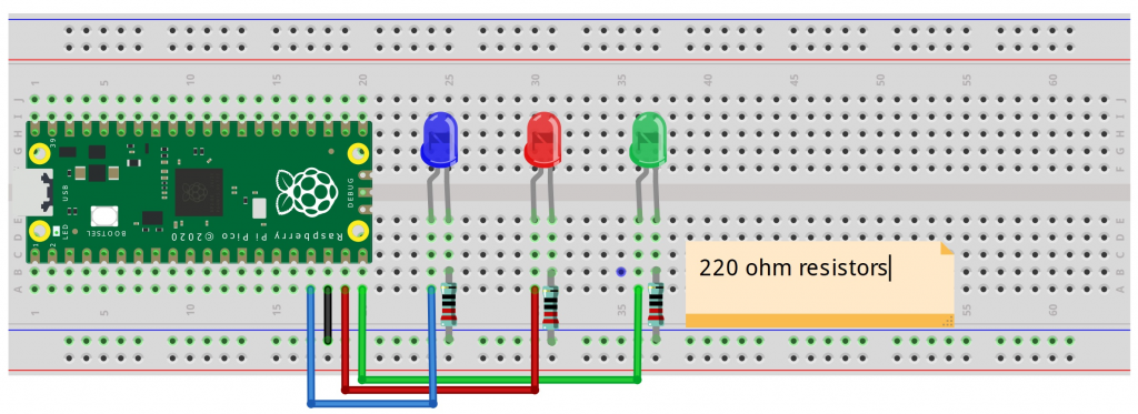
I was able to follow instructions, and got the python program to run. Issue is that I have a logic flaw in how current is flowing, and specifically about positioning of resistor. See below.
Taking a deeper dive into understanding the Python Code:
Reference: (https://docs.micropython.org/en/latest/library/machine.html)
from machine import Pin
-Machine is the Raspberry Pi hardware which can return specific machine-level data
-The machine is considered a module and has various functions that can be passed to the program with hardware information. Caution is advised, as it can get granular and can damage the hardware if done incorrectly.
-Getting acclimated to terminology but Pin is part of a class. The pin object controls various pins of GPIO (general purpose input/output), which are pins I’ve seen on the board. The flow can go either way, with PIN IN or PIN OUT
import utime
-While it appears that utime (specific to micropython) is part of the machine module, it’s not.
-Utime is to do with time-related functions, such as delays and time intervals
led_green = Pin(15, Pin.OUT)
-led_green is a variable
-PIN is a function, sending a message OUT from the hardware, and has two parameters, including which pin and if it’s OUT or IN
-In this case, Pin 15 sends signal to the Green LED to turn on
led_red = Pin(14, Pin.OUT)
-In this case, Pin 14 sends signal to the red LED to turn on
led_blue = Pin(13, Pin.OUT)
-In this case, Pin 13 sends signal to the blue LED to turn on
while True:
-This creates an infinite loop, which requires manual intervention to stop
-There are several lines of code that go in sequence, and then loop back to the top again
led_green.on()
-This turns the green LED on.
-This also means sending a HIGH logic level to the pin (more energy/electricity); a high voltage state
-There are several ways of doing this: led_green.value(1) or led_green.value(true)
-In our scenario, there is a dedicated method of turning it on with: led_green.on()
utime.sleep(1)
-This function, specific to MicroPython, will pause execution for 1 second
led_green.off()
-Green LED turned off
led_red.on()
-Red LED turned on
utime.sleep(1)
-Pause execution for 1 second
-Rest of command are obvious:
led_red.off()
led_blue.on()
utime.sleep(1)
led_blue.off()
Understanding current flow and positioning of resistor in the schematic:
-Component of the LED is long led (Anode) and short leg (Cathode).
-The schematic shows a flow from the Microcontroller Pin to the LED to the resistor to Ground.
-I’m reading that the positioning of resistor (either before or after LED, doesn’t matter as long as everything is between Microcontroller Pin and Ground.
-The consensus is that it doesn’t matter, but I need to read up again on: ohm’s law and kirchhoff’s laws