Nebula Raiders – Day2

Needing to load some libraries

Went to: https://craftingtable.com/pages/downloads

Needed lcd_api.py and i2c_lcd.py

Within Thonny:

-File, open and navigate to each file

-Open on computer

-Save As and save to Raspberry Pi Pico and name it the same. It then shows next to the first library I saved.

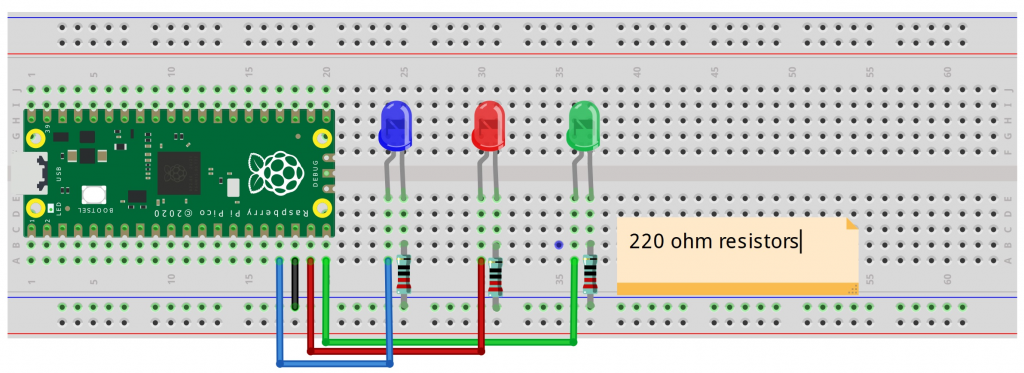
Wired it up and it worked. Now I have a 2 line LCD output device working

Task: Attach the LCD1602 display to the Raspberry Pi Pico using the I2C interface (SDA to GP0, SCL to GP1).

Code:

from machine import I2C, Pin
import utime
from lcd_api import LcdApi
from i2c_lcd import I2cLcd
 
I2C_ADDR = 0x27
I2C_NUM_ROWS = 2
I2C_NUM_COLS = 16
 
i2c = I2C(0, sda=Pin(0), scl=Pin(1), freq=400000)
lcd = I2cLcd(i2c, I2C_ADDR, I2C_NUM_ROWS, I2C_NUM_COLS)
 
messages = [“Nebula Raider”, “Comm System OK”, “Incoming Msg”, “Awaiting Command”]
 
while True:
    for message in messages:
        lcd.clear()
        lcd.putstr(message)
        utime.sleep(3)

Q: What are lcd_api.py and i2c_lcd.py, which I needed to download from CraftingTable?  Libraries?

Q: What is an LCD1602 display? 

A: https://docs.sunfounder.com/projects/ultimate-sensor-kit/en/latest/components_basic/21-component_i2c_lcd1602.html (where I’ve used some of their documentation for my understanding).

A: It’s an LCD1602 IIC/I2C Blue Backlight Display, with 2 lines.    A 16×2 LCD means it can display 16 characters per line and there are 2 such lines. In this LCD each character is displayed in 5×7 pixel matrix. The I2C module has a built-in PCF8574 I2C chip that converts I2C serial data to parallel data for the LCD display.

A: The PCF8574 device provides general-purpose remote I/O expansion for most microcontroller families by way of the I2C interface [serial clock (SCL), serial data (SDA)].

A: More detail:

An I2C LCD1602 consists of a normal LCD1602 and an I2C module that is attached to the back of the LCD. The I2C module is a chip that can expand the I/O ports of the Raspberry Pi using the I2C protocol. The I2C protocol is a serial communication protocol that uses two wires: SDA (serial data) and SCL (serial clock). The I2C protocol allows multiple devices to communicate with each other using only two wires and unique addresses.

The I2C module converts the signals from the Raspberry Pi into commands for the LCD. The LCD has 16×2 cells that can display characters or symbols. Each cell consists of 5×8 dots that can be turned on or off by applying voltage. The LCD can display different characters or symbols by turning on or off different combinations of dots.

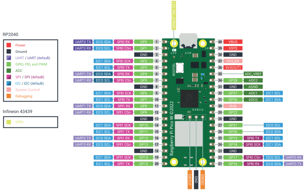
Q: Why is the GP0 (SDA) port part of PIN1 on RPi?

Q: Why is the GP1 (SCL) port part of PIN2 on RPi?

Q: Why does the Python code have SDA=Pin0 and SCL Pin1, when the schematic is PIN1 and PIN2?

Q: What is VBUS on Raspberry Pi stand for.  I know it’s for power.  On the Display board it is labeled VCC

A: The VBUS port on the Raspberry Pi Pico W is the 5V power input from the USB port and is connected to the micro-USB connector. It can be used to power the Pico when it’s plugged in, and you can also use it to source 5V power to an external circuit. Important: Do not connect a second power supply to VBUS if the Pico is already powered via USB, as this can damage either power source.  When the Pico W is plugged into a USB power source, the VBUS pin receives that 5V, which is then used to power the board.  The amount of current available from VBUS depends on the power source. Powering external circuits: VBUS can be used as a 5V output to power external components or devices, but only when the Pico is connected to and powered by a USB sourceAlternative to USB: You can also connect an external 5V power supply directly to the VBUS pin (pin 40) instead of the USB port. However, you must not simultaneously connect another power supply to the USB port to avoid back-powering either source.

Pinouts and wiring:

Pin1: SDA (on back of display board) goes to PIN1 of Raspberry Pi.  Schematic is GPO and ‘I2CO SDA’

Pin2: SCL (on back of display board) goes to PIN2 of Raspberry Pi.  Schematic is GP1 and ‘I2CO SCL’

Pin23: GND (on back of display board) goes to PIN23 of Raspberry Pi.  Schematic is GND. 

Pin40: VCC (on back of display board) goes to PIN40 of Raspberry Pi.  Schematic is VBUS.  This must be Power. 

Examining the code, for understanding:

from machine import I2C, Pin
-Now we’re bringing in ability to both work with PINs on the Raspberry Pi board and also the I2C port location on the board
-The I2C (Inter-Integrated Circuit) is a bus that allows serial communication over two wires (using a communications protocol) for short-distance data communication
-In our scenario, I have a Raspberry Pi Pico WH and a LCD display device that displays 2 rows of 16 characters. 
 
import utime
-We saw this before, and allows us to interrupt the action, for example, to pause things
 
from lcd_api import LcdApi
 
from i2c_lcd import I2cLcd
 
I2C_ADDR = 0x27
I2C_NUM_ROWS = 2
I2C_NUM_COLS = 16
 
i2c = I2C(0, sda=Pin(0), scl=Pin(1), freq=400000)
lcd = I2cLcd(i2c, I2C_ADDR, I2C_NUM_ROWS, I2C_NUM_COLS)
 
messages = [“Nebula Raider”, “Comm System OK”, “Incoming Msg”, “Awaiting Command”]
 
while True:
    for message in messages:
        lcd.clear()
        lcd.putstr(message)
        utime.sleep(3)
Posted in Uncategorized | Leave a comment

Nebula Raiders – Day1

 
from machine import Pin
import utime
 
led_green = Pin(15, Pin.OUT)
led_red = Pin(14, Pin.OUT)
led_blue = Pin(13, Pin.OUT)
 
while True:
    led_green.on()
    utime.sleep(1)
    led_green.off()
    led_red.on()
    utime.sleep(1)
    led_red.off()
    led_blue.on()
    utime.sleep(1)
    led_blue.off()

I was able to follow instructions, and got the python program to run.  Issue is that I have a logic flaw in how current is flowing, and specifically about positioning of resistor.  See below. 

Taking a deeper dive into understanding the Python Code:

Reference: (https://docs.micropython.org/en/latest/library/machine.html)
 
from machine import Pin
-Machine is the Raspberry Pi hardware which can return specific machine-level data
-The machine is considered a module and has various functions that can be passed to the program with hardware information.  Caution is advised, as it can get granular and can damage the hardware if done incorrectly.
-Getting acclimated to terminology but Pin is part of a class.  The pin object controls various pins of GPIO (general purpose input/output), which are pins I’ve seen on the board.  The flow can go either way, with PIN IN or PIN OUT
 
import utime
-While it appears that utime (specific to micropython) is part of the machine module, it’s not. 
-Utime is to do with time-related functions, such as delays and time intervals
 
led_green = Pin(15, Pin.OUT)
-led_green is a variable
-PIN is a function, sending a message OUT from the hardware, and has two parameters, including which pin and if it’s OUT or IN
-In this case, Pin 15 sends signal to the Green LED to turn on
 
led_red = Pin(14, Pin.OUT)
-In this case, Pin 14 sends signal to the red LED to turn on
 
led_blue = Pin(13, Pin.OUT)
-In this case, Pin 13 sends signal to the blue LED to turn on
 
while True:
-This creates an infinite loop, which requires manual intervention to stop
-There are several lines of code that go in sequence, and then loop back to the top again
 
    led_green.on()
-This turns the green LED on. 
-This also means sending a HIGH logic level to the pin (more energy/electricity); a high voltage state
-There are several ways of doing this: led_green.value(1) or led_green.value(true)
-In our scenario, there is a dedicated method of turning it on with: led_green.on()
 
    utime.sleep(1)
-This function, specific to MicroPython, will pause execution for 1 second
 
    led_green.off()
-Green LED turned off
 
    led_red.on()
-Red LED turned on
 
    utime.sleep(1)
-Pause execution for 1 second
 
-Rest of command are obvious:
    led_red.off()
    led_blue.on()
    utime.sleep(1)
    led_blue.off()
 
Understanding current flow and positioning of resistor in the schematic:
 
-Component of the LED is long led (Anode) and short leg (Cathode). 
-The schematic shows a flow from the Microcontroller Pin to the LED to the resistor to Ground. 
-I’m reading that the positioning of resistor (either before or after LED, doesn’t matter as long as everything is between Microcontroller Pin and Ground. 
-The consensus is that it doesn’t matter, but I need to read up again on: ohm’s law and kirchhoff’s laws
 
Posted in Uncategorized | Leave a comment

Nebula Raiders (MicroPython)

I put the Arduino project on hold for a bit, while I broke out another project from Crafting Table (formerly inventr.io) that integrates the Raspberry Pi Pico WH. I’m heading towards another project (in future) with building a Raspberry Pi 5 system with AI board.

20251011 Basic setup steps:

Current Mac OS (10.13.6, MacOS High Sierra:

-This is where I’ll have some workarounds needed, because I remembered I needed to have Thonny version 4.1.4 (released 20231119), as the newer version doesn’t work on this MacOS. And, I can’t upgrade the MacOS because the hardware is circa 2011.

Firmware install:

-Downloaded the firmware from CraftingTable

-Held down BootSel button and plugged in the USB cable to Mac

-Dragged the firmware file over to the folder that appeared

-Had to unplug the cable and back in again, in order for Thonny to recognize the Raspberry Pi Pico

-MicroPython 1.26.1 (release 20250911)

Picozero library:

-Instructions say go (inside Thonny) to Tool, Manage Packages, and search for picozero

-That only returns something called Pickle, and not picozero by PyPy

Note: I read somewhere that this was fixed in the newest version of Thonny, but I can’t use that

-On crafting table, someone posted to go to https://pypi.org/project/picozero#files and download the picozero 0.4.2 file (picozero-0.4.2.tar.gz). Note: This version I’m also seeing on other sites.

NOTE: That didn’t work for me, as the .tar.gz. file wasn’t clickable (grayed out). Also, someone on boards posted an issue with having a Mac, and needing to go to Github to download the picozero.py file.

“Tools/Manage Packages… does not work for me. (Using a Mac) I downloaded picozero from github, saved the file as picozero.py, then went to View, clicked on Files, went searching for my new picozero.py file, right-clicked on it, and chose Upload to… It seemed to work. But I still can’t find picozero in Tools/Manage Packages.”

Referencing this for instructions:

https://picozero.readthedocs.io/en/latest/gettingstarted.html

Instructions like this annoy me – “Either clone the picozero GitHub repository or copy the code from the picozero.py file and save it on your main computer.”

-They don’t say how you clone something from GitHub…

From the list of repositories, click the repository you want to clone. To select the local directory into which you want to clone the repository, next to the “Local Path” field, click Choose… and navigate to the directory. At the bottom of the “Clone a Repository” window, click Clone.

How to clone a repository:

https://docs.github.com/en/repositories/creating-and-managing-repositories/cloning-a-repository

Terminal; went to a folder

git clone https://github.com/RaspberryPiFoundation/picozero.git

Well… that was a pain.

I think I resolved it by just focusing on the file ‘picozero.py’

There are instructions to open the folder and find the file for picozero.py (within Thonny); right click; upload. That places picozero.py within Thonny and you can write code that references the library.

Within Manage Packages, it still doesn’t show picozero.

Posted in Uncategorized | Leave a comment